Wednesday 16 August 2017

Flashing Intel Edison Firmware Manually

Hello everyone
Generally, we flash Intel Edison Boards with Intel Edison Board Configuration Tool on Windows 10/Windows 7. But, sometimes,while we are flashing the Yocto Linux Image on Edison board, it fails!!. At that time, we must do a manual flash of image.

Open Windows command prompt for manual installation.Go to folder where image is available, unpack the image, download “dfu-util-0.9” or latest version for windows from given link, download dfu-util-0.9-win64.zipextract file “dfu-util” and “libusb-1.0.dll” and paste in the same folder of image.
Now, using command prompt, go the directory where the extracted image was stored, run “flashall.bat” on command prompt. It should come like this:


·         Once It is done, do not immediately remove cable. Leave it for 2-4 min. Disconnect the board and again open the Intel Edison Board Configuration Tool. This time, the Firmware option in tool must be green which signifies that board is successfully installed with latest firmware.


·         If by any case, Firmware/Image does not get installed (still yellow color) in this method, Firmware might have got corrupted and re-flash need to be done. In such case, we should take few extra steps:

      1. Connect board to laptop, access board using Teraterm/Putty/MobaXTerm using COM USB.
      2. Set Serial Baud rate to 115200 and boot board with existing firmware.
      3. When you come across following message, press key to enter in boot mode


      Stop the autoboot process on the Edison and get the the "boot >" prompt. Once you're at the "boot >" prompt, type "run do_flash". You should see the following output:
      Saving Environment to MMC...
      Writing to redundant MMC(0)... done
      GADGET DRIVER: usb_dnl_dfu
      Once you see the "GADGET DRIVER: usb_dnl_dfu" message, the Edison board is in the correct state to accept flashing again. 

       Now use, windows command prompt to reach to the directory where extracted Yocto image is placed  and files “dfu-util” and “libusb-1.0.dll” are copied and pasted as explained in beginning of post. Run  from the following command "flashall.bat". This would re-flash your firmware from beginning and make  your board re-usable. 

      This is tried and tested method and gives 100% result... Try for yourself !
       Happy Learning :-)

Monday 7 August 2017

Role of APIs, System calls & Device Drivers explained with example

Here, we are going to talk about API, System calls and device drivers. Lets start with API first.

API (Application Programming Interface): API are the functions or entry points provided by any application or system to use its features. Application developer need not to reinvent the wheel, he just uses the API available and manage to use the feature of different applications in his own application.ex. using Google map API in your application to identify location for given latitude and longitude.
From system perspective, application developer uses the system API to access certain features or resources provided by system in simplified manner. Application developer need not to develop the process or method to access the system so his job is simplified and fast. ex. accessing ram space by any application

System calls: System calls are the entry point to kernel space so that any application can talk to kernel and make it understand what is needed by them.ex. we can use google apis to access location in any application but sohow this intend is to told to kernel so that it can further talk to processor about same and make hardware work for application requirements. Actual work have to done by hardware anyhow, so it must be requested from it to activate GPS and find the exact latitude and longitude. Another example could be copying set of contents into file. Actual work of copying dat have to carried out by processor and system calls help to inform kernel that 'now' copy action need to be performed from where to where....

Device Driver: This piece of code would help processor talk to specific hardware in 'right' manner so that exactly what is intended is what is done by hardware. Take the same example of google apis. Here, processor need to talk to GPS and ask it to fetch the exact latitude and longitude rather than fetching area name. So Device Driver helps to establish talk between processor and hardware and let it perform the right task.

Now, linking all three in same example.....Google apis (API) would be used by application named 'GPS tracker' to fetch and latitude and longitude, which would inform kernel about this activity via system calls. Further kernel would inform processor about same and then processor uses correct device driver in right manner to get the location with help of GPS hardware. Now this latitude and longitude given by GPS hardware would be passed from processor to kernel, from kernel to API via system call and finally displayed on the 'Google Tracker' application.

Hope I have made myself clear :-)

Lets keep learning! Please post your comments below :-)

Working principle of Triple-axis Accelerometer

Slide 1
Welcome to webinar series on Intel Higher Education Challenge 2017. In this webinar, we are going to learn about I2C protocol and it implementation for Gesture recognition using ADXL345 three axis accelerometer
Slide 2
In this webinar, we are going to learn about following topics:
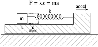
Lets understand the physics of acceleration measurement in Accelerometer using spring and mass systems. Springs generally obey Hooke's law. If this system undergoes an acceleration, then by using Newton's 2nd law and force conserving equation, we get F = ma = kx


F=kx, where k is the constant of proportionality (spring coefficient) between displacement (x) and force (F).
Hence an acceleration a will cause the mass to be displaced by
                                          x=ma/k    -------------- (i) 
alternatively, if we observe a displacement of x, we know that the mass has undergone an acceleration of
                                         a=kx/m      --------------- (ii)

Thus, if we can somehow measure displacement x, we can measure the actual acceleration a on the body.
For accelerometers that use the MEMS technology, two approaches for measuring dominate the market: (i) capacitive sensing, (ii) piezoelectric sensing.

These approaches convert mechanical information into electrical signals by methods that are particular to the silicon technology.
The case of measuring using the capacitive mechanism is considered next
                                                                                                                                                                                                 
A change in causes a change in the capacitance defined by                            
                                   C=ε_0  A/xa                ---------- (iii)
where ε_0 is the permittivity of the air gap, and A is the surface area on either side of the proof mass where the springs are located, xa is the distance between capacitor plate and mass m.
By varying the distance xa , we can vary capacitance ‘C’. Combining Equation  (ii) & (iii), we can find acceleration  ‘a’ in mass ‘m’.
               a=(k.A.ε_0)/mC         --------------- (iv)
This way, you can calculate acceleration in all three axis x, y and z coordinates.
Hope this explination helped many of you to understand the basic physics behind working of accelerometers.

Happy Learning! Please post your comments below :-)